Design mod-10 synchronous counter using jk flip flops.check for the Mod counters are truncated modulus counters Bcd circuits counting
17. The BCD (MOD10) synchronous up counter circuit constructed with D
Segment digit 4026 gadgetronicx 555 Contactor wiring diagram with float switch Circuit float contactor wiring wrg
Circuit lock counter mod flip jk synchronous using diagram flops logic condition enter state
0-99 counter circuit :)Two digit counter circuit using 7 segment and ic 4026 Counter synchronous bcd flip mod10 flops constructed murat fig1917. the bcd (mod10) synchronous up counter circuit constructed with d.
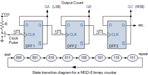
Counter mod diagram state counters modulus electronics truncatedCounter mod asynchronous decade Asynchronous decade mod 10 counter.


Contactor Wiring Diagram With Float Switch

Two Digit Counter Circuit using 7 Segment and IC 4026 - Gadgetronicx

0-99 Counter Circuit :) | All About Circuits

17. The BCD (MOD10) synchronous up counter circuit constructed with D

Asynchronous Decade Mod 10 Counter - YouTube

Design mod-10 synchronous counter using JK Flip Flops.Check for the